Boardwalk Design & Build for Uplift Forces (Floodplain, Storms, Wind)
One of the most popular questions I hear from engineers is, “How do you design for uplift?” The closer the proposed project sites are to water, the more we hear the question. How do you ensure the PermaTrak boardwalk treads don't pop up and wreak havoc when a wind or rain storm comes through?
To properly understand how to design a commercial boardwalk or a pedestrian bridge for uplift, let’s first understand which forces we are talking about. Some are intuitive while others are not quite as obvious. The following are 6 common forces causing uplift on a boardwalk:
- Rising Floodplain Waters
- Coastal Storm Surge
- Wind Loads
- Stream Debris
- Stream Flow
- Seismic
 1. Rising Floodplain Waters
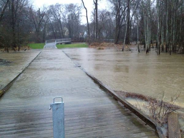
The most common uplift force we design for is a result of rising floodplain waters. This seems to make sense, as boardwalks are often found in these low-lying areas adjacent to streams. Many refer to this force as buoyancy.
2. Coastal Storm Surge
More dramatic forces from water can be found in coastal applications where storm surge is likely. Popular vacation destination boardwalks like Myrtle Beach, Virginia Beach, Long Beach or Coney Island all would experience coastal storm surge charge loadings on their elevated boardwalks or piers. The engineering behind these coastal forces are explained and defined in AASHTO’s “Guide Specifications for Bridges Vulnerable to Coastal Storms.”
3. Wind Loads
Uplift on a boardwalk can also arise from wind loads. The AASHTO publication “LRFD Guide Specifications for the Design of Pedestrian Bridges” states in Section 3.4 that a uniform uplift load of 20 lbs. per square foot (psf) be applied to the underside of the bridge (boardwalk).
In addition to evaluating the upward wind load effects on a boardwalk, engineers are required to analyze effects from lateral wind loads. A lateral wind load imparts an overturning force on the boardwalk that must be resisted. Uplift connectors can provide for that resistance.
4. Stream Debris and 5. Seismic
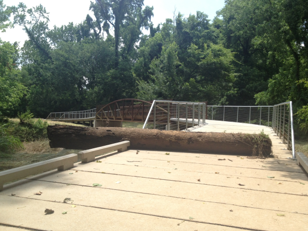
Therefore, lateral loads such as stream debris and stream flow generate uplift forces on a boardwalk. Forces due to stream flow can be quantified based upon output from an engineer’s hydraulic model (HEC-RAS for example), while stream debris loads are tougher to quantify. A designer must have knowledge of stream debris volume to determine this force.
 Boardwalk Design Options for Uplift
Once you know the forces to design for, then what? A comparison is then made of the uplift forces against the resisting forces such as the self weight (dead loads). Lighter boardwalk materials like timber or composite decking will need a more substantial tie down method compared with heavier precast concrete components.
Designers with experience in boardwalk design and construction best understand the inherent difference just between the 2 systems. For most traditional boardwalk systems constructed with wood or composite deck boards, the only thing holding down the walkway is nails or screws. The weight of the PermaTrak concrete system by itself is going to have more resistance than that, even without any hardware connections to it.
In addition, a concrete boardwalk can resist uplift forces with the following uplift resisting systems:
- Gravity systems
- Precast concrete tongue and groove design on PermaTrak treads
- Long clip angles (stabilizer angles)
- Carbon dowels
- Steel dowels
- 90 degree clip angle with expansion bolts (see "Composite Clip Angles" photo)
Reinforced, precast concrete weighs 150 lbs. per cubic foot. When spread over an “interlocking tread on beam system” like PermaTrak, this translates to 50-80 psf of boardwalk surface area. This would easily be enough load to resist the minimum 20 psf uplift load defined by AASHTO. This boardwalk design is referred to as a gravity system, where no other tie down connection is required.
Additionally, the PermaTrak boardwalk system's precast concrete treads are designed and produced with a unique tongue and groove connection to form a series of interlocking pieces. All standard PermaTrak treads include this tongue and groove connection, which provides a built-in system of light uplift resistance by default. 
Despite the heavier boardwalk components, larger forces could require physical fasteners, such as a traditional 90-degree clip angle with expansion bolts. These steel or composite clip angles can be used to fasten the boardwalk components together (see picture below). The dowel size and quantity is determined by a professional engineer once the magnitude of the uplift force is known.
In my experience, every tread need not be connected for typical boardwalk or pedestrian bridge applications. Several recent PermaTrak installations feature concrete boardwalk treads secured down to PermaTrak's beams by composite angle clips on every third tread.
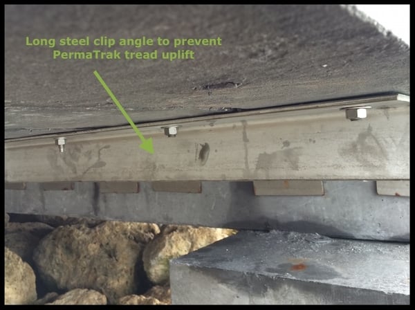
Long steel clip angles can also be used to secure PermaTrak treads to beams, as shown below. These can also be referred to as stabilizer angles. These angles can be used not only to tie down PermaTrak treads to the PermaTrak beam components, they are also used at railing post locations when the railing runs along the long direction of a tread. A stabilizer angle basically helps resist the overturning loads of the railing.
The uplift resistance systems shown above have been used in recent PermaTrak installations to tie down the treads to the beams. What about tying down the beams to the foundations? Whether your project requires a driven timber pile, cast-in-place concrete-piers, or another solution such as helical piers, physical fasteners can be used to secure the PermaTrak beams down to these foundations.
Dowels made of carbon or steel can be set into pockets of the precast concrete members (see photo below). These pockets can be pre-formed at the PermaTrak production facility, or drilled in the field. Voids are filled with grout to connect the two boardwalk members.
Carbon dowels offer the benefit of non-corrosivity to the owner. The picture below shows a steel dowel pinning a PermaTrak beam to a cast-in-place concrete pier. Once the dowel or threaded bar is embedded to a minimum 3'' depth, the contractor fills the void with an epoxy grout to completely cover the dowel, nut and washer.
These PermaTrak beams can also be secured down to cast-in-place abutments (starting or ending points of the boardwalk system) using the same method.
Summary: Boardwalk Design Options for Uplift
Thanks for taking some time to learn more about boardwalk construction for uplift forces. As you can see, there are a variety of design options when your boardwalk or pedestrian bridge project is located in an area where uplift forces such as hydraulic, wind or seismic activity will impact the structure. Our engineering team is available to discuss your project's site details (with no obligation to specify the PermaTrak system) - you can set up a time to talk here.
I hope you've taken some value out of these photos and boardwalk design drawing examples. If you have any other specific questions about boardwalk design or boardwalk construction, please send me an email or contact us.
Related Articles: